Panel Saw Digital Readout Adjustment
Is your panel saw digital readout showing a different measurement from the actual panel size? A digital readout (DRO) may require checking or recalibration if the crosscut stop or parallel fence does not position the panel accurately. Follow this guide to help identify the cause before making adjustments.
Request Technical Support Call 1300 4 FORZACommon Causes of Digital Readout Inaccuracy
Selected NikMann S-350 series panel saws are equipped with digital readouts on the crosscut stop and parallel fence. These displays help operators position material for accurate cutting.
If the displayed value does not match the actual cut dimension, the cause may be an incorrect reference point, fence positioning, mechanical movement or a calibration issue. Check the machine setup before changing the digital readout settings.
Check these possible causes when the DRO measurement does not match the actual panel size.
Incorrect Zero Reference
If the digital readout was zeroed at the wrong reference point, all subsequent measurements may be consistently too large or too small.
Check: Confirm the correct reference position according to the machine and readout manufacturer's instructions.
Fence Positioning
The displayed measurement may not match the actual cutting position if the parallel fence or crosscut stop is not positioned or secured correctly.
Check: Inspect fence alignment, locking mechanisms and the physical stop position.
Blade Kerf
The saw blade removes material as it cuts. If the measurement reference and intended finished dimension are interpreted incorrectly, the resulting panel size may differ from the expected size.
Check: Confirm where the measurement is taken and account for the cutting kerf where applicable.
Mechanical Movement or Wear
Wear, looseness or movement in the fence, stop, guide or measuring mechanism can affect repeatability and positioning.
Check: Look for looseness, movement or inconsistent positioning before recalibrating the display.
Digital Encoder or Sensor
Depending on the readout system, an encoder, measuring strip, connection or sensor fault may cause the displayed value to differ from the actual travel distance.
Check: Look for inconsistent readings or interruptions in the displayed measurement.
Calibration Drift
The displayed measurement may become inaccurate following adjustment, maintenance, machine relocation or prolonged use.
Check: Verify the reading against a measured test cut and follow the instructions for your specific DRO.
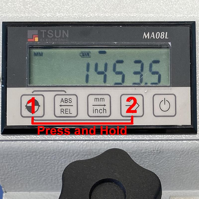
1. Press and Hold - Button 1 and 2 as per attached photo;
2. Screen will change the numbers - for example to 300;
3. Repossition the Cross cut stop to the new value by using magnified glass;
4. Press and Hold Button 1 and 2 as per photo;
5. Now the value on a screen should be the same as the magnified glass;
6. Digital read out is calibrated.
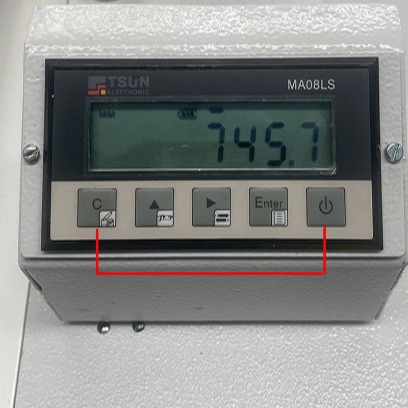
1. Press and Hold - Button 1 and 2 as per attached photo;
2. Screen will change the numbers - for example to 300;
3. Repossition the Cross cut stop to the new value by using magnified glass;
4. Press and Hold Button 1 and 2 as per photo;
5. Now the value on a screen should be the same as the magnified glass;
6. Digital read out is calibrated.
Check the Actual Panel Measurement
Before changing any calibration settings, confirm the size of the finished panel using a reliable measuring tool.
Measure the Finished Panel
Use a suitable steel rule, tape measure or calibrated measuring tool to check the actual panel dimension. Measure consistently from the correct reference edges.
Compare the Displayed Value
Record the digital readout value and compare it with the measured result. Note the direction and amount of the difference.
Repeat the Measurement
Make another measurement using the same setup. Determine whether the difference is consistent or changes between repeated positioning attempts.
Check Both Readouts
If the machine has separate digital readouts for the crosscut stop and parallel fence, check each independently to identify which measurement system may be inaccurate.
Check the Fence and Stop Position
Confirm that the physical measuring and positioning components are operating correctly before recalibrating the DRO.
Inspect the Parallel Fence
Check that the fence is secure and correctly aligned. Confirm that it does not move after being locked into position.
Inspect the Crosscut Stop
Check the stop, measuring scale and locking mechanism. Ensure the stop reaches and holds its intended position.
Check the Reference Point
Confirm the correct reference point for the measurement. Do not assume the zero point should be set at the blade edge without checking the machine's instructions.
Check for Mechanical Play
Look for looseness in guides, slides, stops or related components. Resolve mechanical issues before relying on electronic calibration.
How to Check and Adjust the Digital Readout
The exact calibration procedure depends on the installed digital readout and measuring system. Use the instructions for your machine model and DRO.
Record the Existing Settings
Before making changes, record the current displayed values and any available calibration settings. This helps you document the original setup.
Position the Fence or Stop
Position the relevant fence or stop at a clearly defined reference point, following the manufacturer's calibration instructions.
Verify Against a Known Measurement
Use an appropriate reference measurement to determine whether the readout accurately represents the physical position. Avoid guessing a correction value.
Adjust Using the Correct Procedure
If calibration is required, follow the instructions for the specific DRO system. Do not change encoder parameters or internal settings without the correct procedure.
Make a Test Cut
After the adjustment, make a suitable test cut using approved operating procedures. Measure the finished panel and compare it with the intended dimension.
Confirm Repeatability
Repeat the positioning and measurement check. The readout should provide consistent results within the machine's specified accuracy.
Digital Readout Still Showing Incorrect Measurements?
If the digital readout remains inaccurate after checking the fence, stop and reference point, the issue may require further diagnosis of the measuring system or mechanical positioning components.
Forza Machinery provides woodworking machinery service and technical support for businesses in Melbourne, Victoria and across Australia.
Panel Saw Repairs
Get assistance with panel saw alignment, cutting accuracy, calibration and mechanical or electrical faults.
Panel Saw Repairs →Technical Support
Find additional technical support information for woodworking machinery and panel saw operation.
Technical Support →Maintain Accurate Panel Saw Measurements
Correctly checking the digital readout, reference point, fence position and calibration can help improve cutting consistency and reduce material waste. Contact Forza Machinery if you need help with panel saw servicing or technical support.